September 09, 2011 ( last updated : February 17, 2021 )
canon
astrophotography
dslr
electronics
One of my other hobbies is photography, and whilst I don’t spend as much time with the camera as I would like I still like to have plenty of power. I shoot with a 30D and/or 40D, which uses the old style BP-511/A Canon battery. The dilemna I had is that I would like to power my camera from a 12-14V source (such as a SLA battery) to get plenty of juice, but I need to provide the requisite 7.4V expected from the battery.
There are two aspects to this – electronic compatibility and mechanical compatibility. Luckily the electronic compatability is easy (at least on the older models – I can’t speak for the new ones) as you just need to provide the expected 7.4V. Mechanically I looked at a few options such as custom fabrications, but in the end I just settled for the tried and true “crack open a battery that no longer works”.
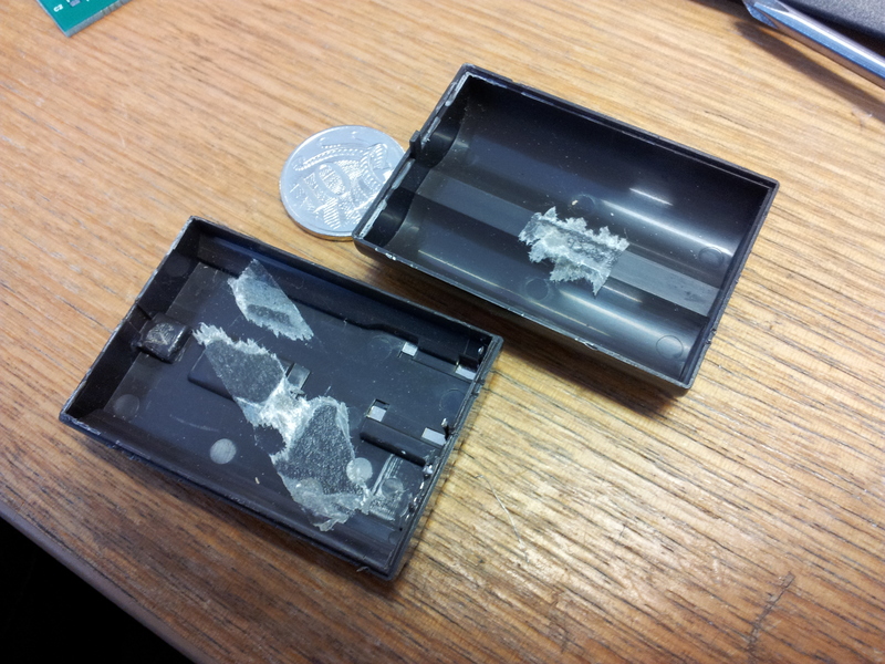
BP-511A Casing after removing cells and control board.
Daniel McCauley of https://www.easternvoltageresearch.com/ used to have a wonderful document that listed the current draw of a 300D when operating in different conditions. Whilst the document has long gone online, I recall that the peak current was in the range of about 1A, albeit for very short periods. It does however provide a rough estimate of the currents involved. I credit him with the original idea behind doing this as well!
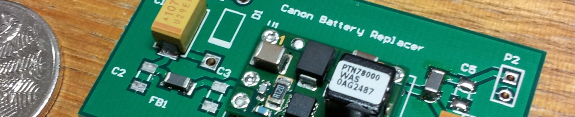
Whilst the original design Daniel provided used a standard linear regulator, I figured that the size of switch mode supplies had decreased enough such that it should be possible to mount an entire DC/DC converter inside the battery compartment. This way I can feed in any (reasonable) voltage and the camera will operate happily. Being a touch lazy (and enjoying other things then power supply design) I just grabbed a module off the shelf that was small, and had what I thought would be acceptable specifications (lowish ripple, high efficiency). I settled on the TI PTN78000W module (in the surface mount variety). It was then just a matter of designing a rudimentary board around it that contained a protection diode as well as some input and output filtering. If you would like a copy of the schematic feel free to contact me!
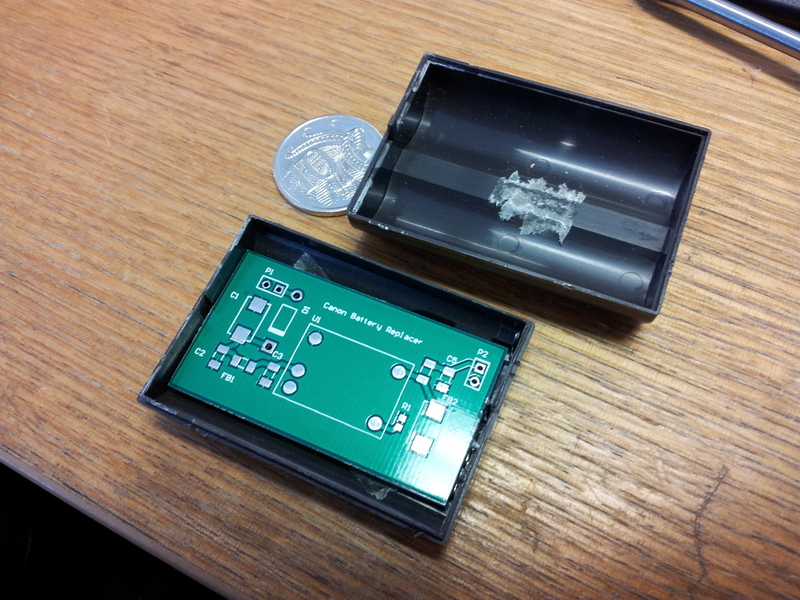
Testing the new DC/DC converter board for fit - and it does!
I opted to get this board professionally made as I wanted a nice reliable final product that worked in some pretty horrid conditions (cold, dampy, hot, dusty – all the usual suspects!). It was then time to get the hot plate out and do some soldering:
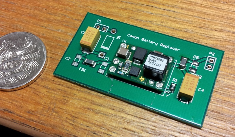
The board is assembled except for 3x 2.2uF 0805 caps (and the cable connectors!).
And that is where this first post ends – I need to order some caps that I apparently don’t have in my junk box. I’ll post again once it is assembled and tested.
Note: I did contemplate purchasing a non genuine one from eBay, but I liked the idea of having something that I knew was a bit more reliable. Ironically enough I trust my own fabrications more when connected to expensive equipment then the really cheap knockoffs.
Originally published September 09, 2011 (Updated February 17, 2021)
Related posts :